Axial flow fans
Production description
A large selection of outlet positions, casing geometries, casing thicknesses and materials is available for the various impeller types. The following is a description of the standard product range; a very flexible production allows special requirements to be met as well.
Standard Accessories
- Shaped inlet
- Fire damper
- Protection grill
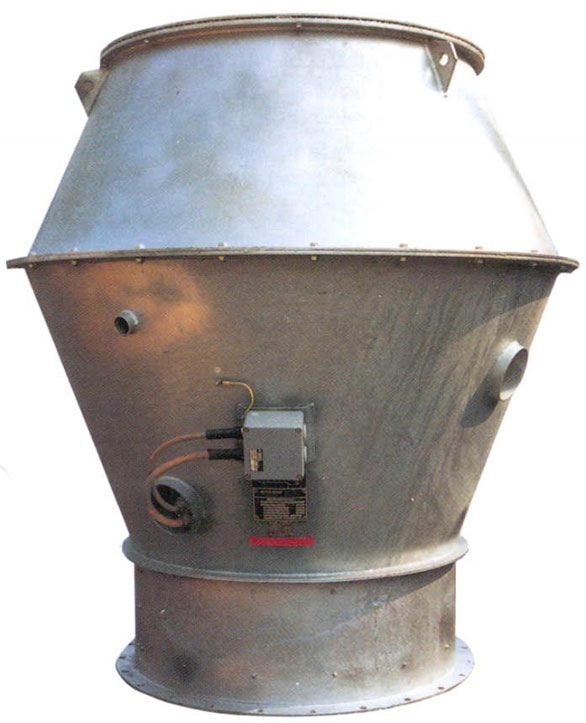
- Mushroom cowl
- Feet for horizontal/vertical position
- Vibration attenuator
- Jet cowl
- Flexible connection
- Counter flange
- Silencer
- Variable inlet vane
The specific design of a fan is mainly determined by the installation in which it will be used. Beside the physical properties such as pressure, volume flow rate and temperature, the operating conditions and the installation location are of major importance (Reference DIN 24 163 for a complete description of the input parameters for a fan specification). The actual fan dimensions are mainly determined by the motors and accessories used.
Our axial flow fan range is distinguished by a large number of different standard designs. The different impeller hub-diameter rations enable us to satisfy a very large range of volume flow rate/pressure combinations for most types of installations.
The quick selection charts/nomogramm sheets and our dimension sheets give an overview over the most commonly used axial flow fans. In addition to the shown standard fans, we also manufacture a large number of special designs, e. g. explosions proof, pump room fans, shock proof fans, smoke extract fans, jet fans etc. In case of demand for special fans please inquire.
The fan selection graphs make allow a quick selection of the axial flow fans normally used at 50 Hz. They provide the fan type, the size, number of poles of the motor, the shaft power and the sound power.
The following gives a brief description of our axial flow fan casing designs.
| Inlet Size | 250 bis 3550 mm |
| Casing thickness | 1,5 bis 20 mm |
| Impeller types | P, N, M, X, Y (adjustable pitch) |
| Motor frame size | 63 bis 710 (0.1 kW bis 2.0 MW) |
| Drive type | Coupling-, belt- or direct drive |
| Position | A, AU, AD, B, BD, BU according to Eurovent |
| Casing form | Short/long casing, swing out with/without shaped inlet |
| Surface treatment | Primer, finish, hot-dip galvanized, on request |
| Material | |
| - Impeller | Corrosion resistant cast aluminium, Steel, special materials |
| - Casing | Steel, aluminium, special alloys |
| Special design | Flame-proof, high temperature, shock proof, according to requirements |
Design
The design of an axial flow fan is described by the casing length, the fan diameter (inside dimension), casing thickness, motor/terminal box design and the accessories. All our axial flow fans can be supplied as a standard with 2 to 10 mm casing gadge and a diameter from 250 mm to 2800 mm.
The application and the location of the fan determines the gadge. For example 2 to 4 mm is used in normal industrial installations, 3 to 6 mm below deck on ships and 8 to 10 mm above deck or in heavy duty industrial applications.
The specifications of the installation determines the design. The following gives some guidelines.
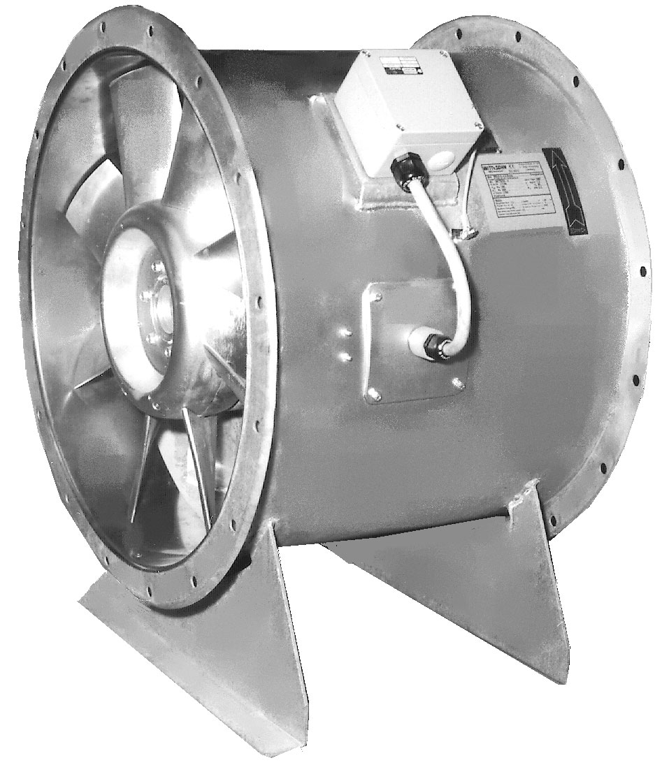
Normal design (long casing)
For many applications (industrial or ship building) the designs A and G (GT for jet fans) are used. The designs have a long casing that fully encloses the motor, with an external terminal box. The design A has a service access to allow minor servicing. A special case of design G (GT for jet fans) is the design GD (GDT), which has an inlet cone instead of a flange for free inlet.
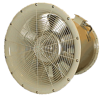
Normal design (short casing)
For many ventilation applications a small fan is mounted in a duct system. The designs D and W (DD and WD with inlet cone for free inlet) are used for that. They have a short fan casing with the motor partly outside the casing.
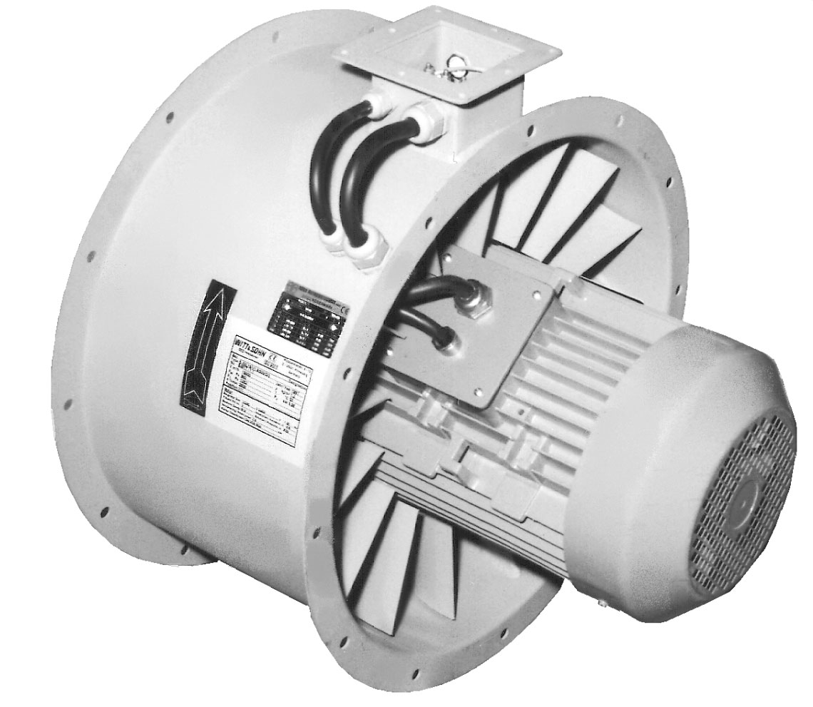
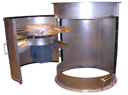
Ease of Service Access
In some installations it is important to be able to often access the impeller or the motor without disassembling the whole system. For this kind of applications we recommend our design B or W, WD. By having the impeller /motor mounted on a swing out type access door, all type of service and maintenance can easily be done.
Bellmouth fans
For free inlet operation fans with free inlet as DD or E should be choosen.
Reversible Fans
In principle, all fans are reversible, with greatly reduced performance data.fans marked R (e.g. GDR) with special impellers are almost completely reversible.
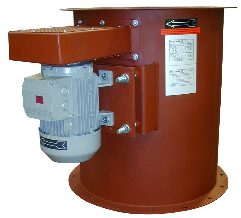
External motor
For systems where the motor should not be placed in the air flow, we offer the S (motor on the fan shaft) and T (motor on its own foundation) designs. Both operate the impeller via a V-belt drive.
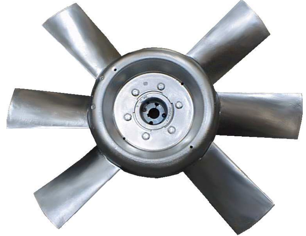
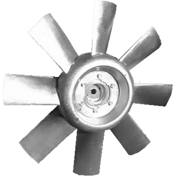
Impeller programme
Our impellers have all aerofoil blades with high efficiencies and favorable noise ratings. Of course electric motors are normally supported symmetrically, without feet disturbing the flow. The blade angle can be adjusted at standstill, a big advantage when for example the duct system is modified. The aerodynamically shaped impellers are made of corrosions resistant cast aluminium alloy. It's low weight gives good life expectancy for the motor bearings. The quick selection tables/nomogramme is an aid for quickly selecting the most suitable impeller.
Description of single stage impellers
The standard impeller programme has four main types, N. M, X and Y with 6, 8 or 12 blades. By using guide vanes with 5 or 15 blades a high efficiency at high pressure is obtained.
1 − Low pressure impeller types P6 and P8
This type with 6 or 8 profiled blades is characterized by high efficiency (up to 85%) and very good noise behaviour.
2 − Low pressure impeller N6 and N8
This type with 6 or 8 profiled blades is characterized by high efficiency (up to 85%) and very good noise behaviour.
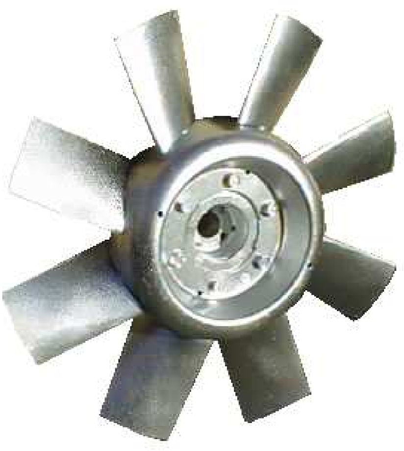
3 − Medium pressure impellers M8 and X8
In order to still achieve good efficiencies (up to 80%) with larger air volumes and higher pressures, we often use M8 or X8 impellers.
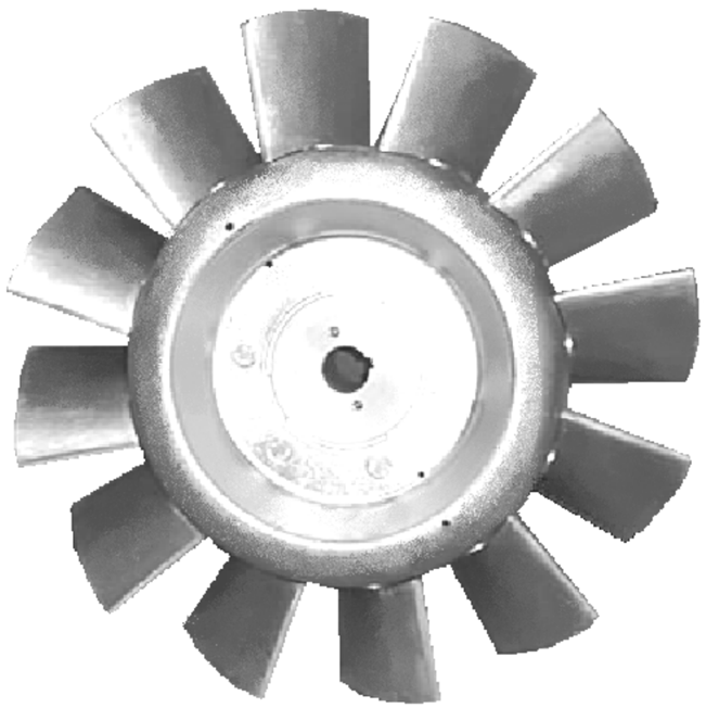
4 − High pressure impellers Y8 and Y12
These impellers combined with 15 bladed guide vanes provide very high pressures for axial flow fans while still maintaining good overall efficiencies.
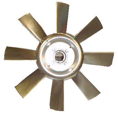
5 − Reversible impeller types PR6 and PR8
These impeller types allow almost 100% reversibility of the air flow without large loss of performance.
6 − Reversible impellers NR8 and MR8
These impeller types allow an almost 100% reversibility of the air flow without great loss of performance.
Multistage axial flow fans
Axial flow fans can also be build in multistage versions to increase to total pressure achieved. Our various impellers with guide vanes can be installed in series. The fans are made by using motors with two shaft ends or two separate motors. The pressures can be added with a subtraction of approximately 15 % for the second stage. The number of possible curves is so waste that they have not been included in this catalogue. If the need arises please send us an inquiry.
Technical guidelines
Materials and Surface Treatments
The fan casings are normally made of heavy gauge plates and structural steel, free from grease and oil and with negligible surface oxidation. They are painted with an epoxy resin iron oxide ground coat. All screws and nuts are galvanised. For seagoing vessels the screw connections of the service access are made of stainless steel or brass.
On request, the casings can be hot dip galvanised or receive a special coating.
The installed motors are usually designed for a temperature range of minus 25 to plus 40 degrees Celsius according to the rules VDE 0530.
Impellers are cast of aluminium and guiding vanes are welded of rolled steel.
The impellers can withstand proofed temperatures 200°C, 2h ¦ 300°C, 2h ¦ 400°C, 2h und 700°C, 90 minutes.
Explosion Proof
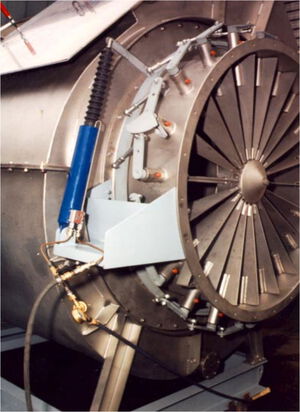
The casing of our explosion proof designs is lined with a spark protection plate of naval brass, which will cause no sparking due to friction or impact with the aluminium impeller. The motor will of course comply with pertinent rules.
Installation Guidelines
Axial fans are quite sensitive against lopsided air supply to the impeller. When different velocities reign in parallel paths of flow, turbulences may occur close to the impeller with important output losses as a consequence. Sharp bends at a short distance from the impeller should be avoided.
In order to avoid a contraction of the air flow with turbulencies near the duct wall, fans should have a conical inlet or a bell mouth whenever they have no duct system on their inlet side. Changes in the cross section of ducts shortly before the fan should, if possible, be carried out in such a way that no flow separations occur.
The fan output may be seriously diminished by cross section reductions shortly after the impeller. This is especially the case for axial fans with an important swirl in absence of guiding vanes.
Upstream flow obstacles should be avoided, as they may create turbulences that lead to an important noise level increase.
Starting Times
The starting time is determined by both the accelerating torque, being equal to the difference between the motor torque and counter torque of the load and by the inertia of the impeller. The motor torque curve may vary considerably from case to case, in spite of existing rules. For the guaranteed starting torque, for instance, VDE 0530 rules allow a tolerance form −15 % to +25 %.
For motors having the rotor class 16 the starting time is roughly:
$ t = \frac {0,7 \cdot M \cdot D^2 \cdot n^2} {10^6 \cdot N} [sec] $
where n is the fan speed in rpm, N the rated motor power in kW, M die mass of the fan in kg and D the impeller diameter.
For belt drive fans n2 is to be substituted by nvent · nmot the product of the blower and motor speeds.
If motor with lower starting torque's are employed, the calculated time is to be multiplied by 1,2 for rotor class 13 and 1,9 for class 10, where n is the number of fan rotations per minute, N the motor power in kW, M the impeller mass in kg and D the impeller diameter in m.
Long starting times should be expected for all axial fans having a lower speed than that of the motor, f. e. by means of a belt drive. In this and also in other cases the installation of relays for extra heavy start may be necessary.
Instability range
The performance curves of axial fans have a more or less pronounced instability range, because of its shape often called saddle. In the range B − C (Fig. 1.6) a small increase of the flow resistance coefficient will cause a considerable decrease of the flow combined with a simultaneous decrease of the pressure produced by the fan. The working point of a fan should, if possible, be placed in its normal working range A − B, where it has the highest efficiency.
The effect of the saddle may be illustrated by means of Fig. 1.6 showing three working points of a fan. They are determined as intersection points of its performance curve with three different air flow resistance curves. These often follow the rule:
$ \Delta p_g = C_{1,2,3} \cdot \dot{V^2} $
where C1, C2, C3 are the flow resistance coefficients. The necessary pressure increases with the square of the flow through a system.
Fig. 1.6 - Determination of the working point of an axial fan is intersection of its characteristic with three different resistance parables.
If we start from curve I and increase the coefficient by 20 %, we obtain curve II. The output in the new working point, defined as product of flow and total pressure, is 10 % lower than before. If the coefficient is increased once more by 20 %, we obtain curve III. The working point now falls into the saddle and the reduction of output is in the example shown 37 %.
Whenever fans work to the left of point B flow separation on the blades may cause these to vibrate considerably, eventually leading to fatigue. Especially for fans working between the points B and C the so called pumping may occur, where the working point on the curve is subject o travel continuously along the curve. This may aggravate the vibrations.
In order to prevent flow separation and pumping, our fans can on request be fitted with antistall rings according to Prof. Eck. The fan curve will be stabilized to the dotted line with much reduced vibration levels.
Output Control/Vane controls
In most cases the use of pole-changing fans is sufficient. Due to the ever cheaper power electronics, frequency converters are increasingly used. It must be noted that the natural frequency of the fan (especially with infinitely variable frequency control) is avoided. It is also advisable to select motor and converter from the same manufacturer to avoid tuning and performance problems.
Frequency converter control
When an axial fan is controlled by a frequency converter care has to be taken, that the fan is not for any length of time in one of it's resonance frequencies. The vibration amplitude must be measured on the motor itself and not on the casing. The resonance frequencies must be blocked, so that they are passed quickly.
At low rotational speeds, i. e. at low motor torque care must be taken, that the fan can not be stopped by a reverse air current, otherwise the motor may be overheated.
Electric current pulses
Especially sudden reversion of the direction of rotation as well as wind milling of axial impellers may cause large current pulses. This may cause disturbances in the electric supply net and unacceptable wear of the electric contacts. The high torque pulses may also harm impellers and electric motors.
Before the direction of rotation is reversed a sufficient run-out period must be allowed for. Wind milling may become so pronounced, that the installation of a motor brake may be recommendable, which only is released briefly before the motor is energized.
When star-delta start is employed the switching over must not be done too early in order to avoid large current pulses.
Tolerances
Selection, prediction and manufacturing tolerances cannot be avoided. The tolerances for fans are summarized in the DIN 24 166. For fans the tolerance class 2 is normally applicable unless otherwise specifically agreed upon.
For special fans (e. g. rubber coated fans, special one-off impellers, gastight design, explosion proof fans etc.) the tolerance class 3 is applicable. In case of doubt please consult one of our sales engineers.
Inlet/outlet disturbances are not included and have to be included separately.
Other tolerance levels than those given in DIN 24 166 must be agreed upon separately in writing.
Tolerances for various tolerances classes
A) Manufacturing tolerances
| Tolerance class acc. to DIN 24166 | 1 | 2 | 3 |
|---|---|---|---|
| Volume flow rate $ \dot{V} $ | ± 2,5 % | ± 5 % | ± 10 % |
| Total pressure increase $ \Delta p_t $ | ± 2,5 % | ± 5 % | ± 10 % |
| Shaft power $ p_w $ | ± 3 % | ± 8 % | ± 16 % |
| Efficiency | - 2 % | - 5 % | - |
| Sound values $ L_w, L_p $ | + 3 dB | + 4 dB | + 6 dB |
B) Measuring tolerances
If the performance data of a fan are checked, the following measurement tolerances apply for measurements on a standard-compliant dynamometer:
Tolerances ISO 13348 - Axial/Radial
| Class | dV | Dp | dPw |
|---|---|---|---|
| AN1 | 1,0 % | 1,0 % | 2,0 % |
| AN2 | 2,5 % | 2,5 % | 3,0 % |
| AN3 | 5,0 % | 5,0 % | 8,0 % |
| AN4 | 10,0 % | 10,0 % | 16,0 % |
Toleranzen ISO 13350 - Jet Fans
| Parameters | Measurem. | Manufact. | Total |
|---|---|---|---|
| Thrust Blow-out | 5,0 % | 1,0 % | 6,0 % |
| Speed Electr. | 10,0 % | 3,0 % | 13,0 % |
| Power | 2,0 % | 3,0 % | 5,0 % |
| Sound level | ISO 13347 | 3,0 % | 3,0 % |
Operating conditions
The tolerances are only valid in the specified working point which is defined by the fan speed, volume flow rate, pressure increase, density and gas composition.
Fan selection tables
Direct Drive 50 Hz, Total pressure:
Direct Drive 60 Hz, Total pressure: